The first category Power Electronics Circuits are Diode Rectifiers which is also called Uncontrolled Rectifiers. These kind of Rectifiers are uncontrollable; means their output can't be controlled. We will discuss the first function of diode then different circuits of Rectifiers.

First of all, let us discuss working of Diode actually how does it work?


 Diode is a device which is made by combining P and N junction with each other, First P and N Type Semi Conductors are formed by Doping of Trivalent Element (P Type) and Pentavalent Element form N Type. When P and N type are combined together they form P-N Junction, at point they combined there forms a depletion reigon.


Electons and holes diffused into each other to make Depletion Reigon i.e voltage barrier
There are two modes of Diode Operations:

1.Reverse Bias
2.Forward Bias

Reverse Bias:

If diode is connected in Reverse manner means if P type of P-N Junction is connected to negative terminal of battery and N type is connected to Positive terminal of battery in this fashion depletion reigon of P-N reigon is increased and diode doesnt allow any current to pass because of Huge Depletion reigon, this depletion is also called barrier.

Summary: No conduction in Reverse Bias Manner

Forward Bias:

If diode is connected in this manner that P type of P-N junction is connected with the Positive terminal of battery and N type connected to Negative terminal, in this fashion depletion region of the diode will be decreased and it will provide path for conduction, there will be drop of 0.7 volts to overcome this very small depletion region.

Summary: Diode will conduct current but with 0.7 constant drop on it in the forward biased configuration.


Types of Rectifier (In Output Terms):

1. Half wave Rectifier
2. Full Wave Rectifier


Half Wave Rectifier:

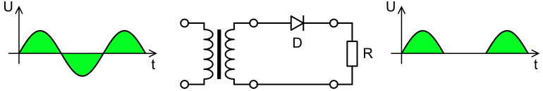
As the name suggests in this type of Rectifier output of wave is only Half Wave of orignal AC signal is converted to DC because in the negative signal diode gets reverse biased and doesn't let current pass.

Average value of DC can be calculated by integrating AC wave i.e V x SinΘ over 2π and take its period 2π so we calculated the average value its found out to be 

Vavg= 0.316 x  Vp

Vavg = Average DC value

Vp= Peak value of AC signal

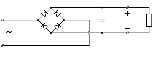
Full Wave Rectifier:

In this type full AC signal is converted to DC even negative signal is made positive by means of Rectification, there are many circuits to do this, but two famous ones are Bridge Rectifier and Centre tap Transformer as you can see in the figure.


Diode bridge alt 2.svg
Other circuit for Full wave is Bridge Rectifier as we can see its bit different than Centre tap, it has also one biggest advantage over Centre, that is centre tapped configuration always divides input voltage into Half and then sent it to the rectifier and in Bridge Rectifier its not the cast, full wave is sent to the rectifier and its gets converted to DC.  

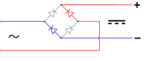
Average Value of Full Wave Rectifier can be calculated same as Half Wave, but its period will be taken π instead of 2π.

Problems in Rectification:

Diode bridge smoothing.svgOne of the problems with this type of rectification is that the output is not the pure DC but it is Pulsating DC, so we cannot use this kind of DC its useless, so this pulsating DC can be smoothed by Smoothing Process i.e connecting Electrolytic Capacitors in Parallel with ouput.


Summary:

As you can see rectification is done by simple diodes, but output can only be depended upon input, we can't control output by any gate or some sort of anything, so that's why these are called uncontrolled rectifiers.


Post a Comment

Please give us feedback in comments here

 
Top